Scan Hippo

A dead telematics box. One live CAN bus.

A 2016 Subaru Outback came with a StarLink module that had outlived the 3G network it needed. Getting the car's stereo working again meant desoldering that module's connector — and the half of it left over carried the car's CAN bus, three power rails, two buttons and two LEDs, already wired into the dash. Scan Hippo is an OBD-II tester built on what the repair left behind: an Arduino Nano ESP32 speaking ISO 15765-4, with a phone app to come.

Not on the App Store Not on Google Play

This site is here to tell the story, not to ship anything. Nothing on this page is a download — see why.

Arduino Nano ESP32  ·  C++ · MCP2515  ·  ISO 15765-4  ·  Apache-2.0

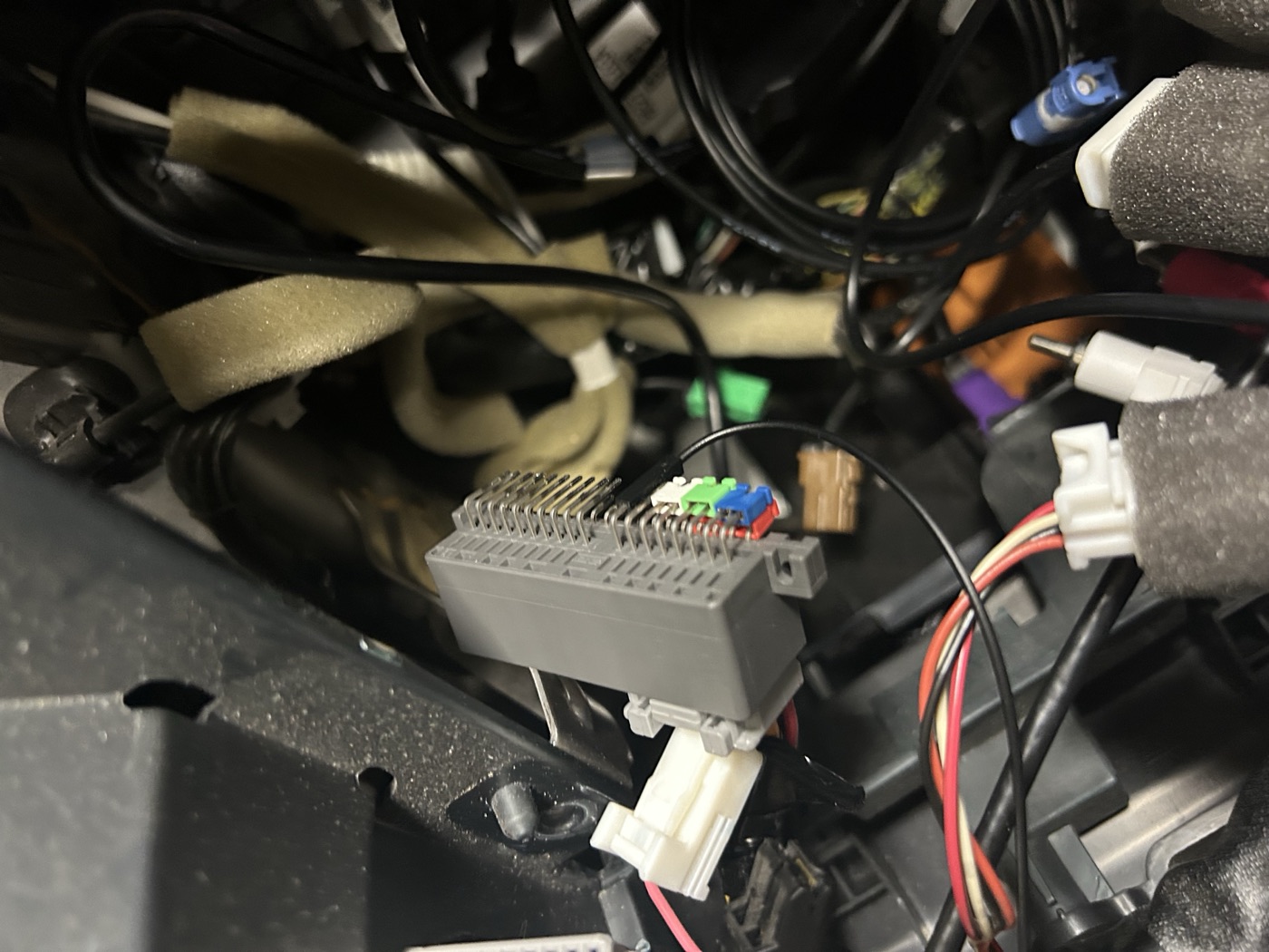
The grey StarLink connector, desoldered from its module, resting among the wiring behind the dash of a Subaru Outback. Its bare pins stand up in two rows.
The connector this whole project is built on, desoldered from the StarLink module and back in the dash.

How a flat battery turned into a CAN bus project

Nobody sets out to build an OBD-II scanner because their stereo stopped working. Every step here was forced by the one before it, and the project is what was left standing at the end.

  1. A 2016 Outback, in good shape, with one known fault

    Bought used. Everything about it was sound except the StarLink telematics module, which was out of service.

  2. The 3G network went away, and the radio never noticed

    First-generation StarLink reaches the world over a 3G radio, and the US carriers finished switching 3G off in 2022. The module has nothing left to attach to — but rather than give up, it scans. Forever. A transmitter hunting for a network that no longer exists is close to the worst case for current draw, and the result is a car that goes flat in days instead of weeks.

  3. The dealer put it to sleep, and the microphone died

    Before the car was sold it went to the dealer, who did something to the module to stop it draining the battery. Whatever it was, it worked. It also left the cabin microphone dead. The speakers still played, so this read as a minor annoyance rather than as a clue.

  4. Which mattered, because StarLink sits in the middle of the audio

    The module is not a peripheral hanging off the stereo. The head unit's front speaker drive enters the module and leaves again on its way to the speakers; the microphone enters and leaves again on its way to the head unit. Subaru's own pinout names them in exactly those terms — Front speaker input LH - on one pin, Front speaker output LH - on the next — so that the module can duck the stereo and seize the cabin for an SOS call. Every one of those lines is a pass-through.

  5. Then the head unit was replaced, and everything went quiet

    The factory head unit came out in favour of a Hamilton Motor Company conversion kit — CarPlay and Android Auto in the original dash opening. After the install, the speakers and the microphone stopped working.

  6. A forum thread explained it exactly

    The answer was on subaruoutback.org: pull the factory head unit and nothing is left to complete the loop. Audio that used to go out to StarLink and come back in now goes out and stops. The module was the bridge, and the bridge is what got removed.

  7. So the connector came off the board

    The module itself was unwanted — it is the connector that matters. Desoldered from the StarLink board, its B half can be bridged pin to pin, tying each input straight to the output it used to feed. Six jumpers, and the arithmetic works out exactly: two front speakers at two polarities each is four, plus microphone signal and microphone ground.

    Pin B8 is the odd one out. MIC 5 V is not a pass-through, it is a supply the factory head unit used to provide, and the CarPlay harness leaves that position unpopulated. It needs a wire run from pin 4 of the radio's harness — an empty cavity from the factory. A crimped pin does it, or a male-to-female Dupont jumper with the plastic shroud pulled off the male end.

  8. And the other half was too interesting to bin

    The repair used only the B side. The A side was still on the bench, and its pinout is an invitation: two separate CAN buses, three power rails, two buttons and two indicator LEDs — on a connector engineered to live in this exact car, already wired, already fused, already in the right place.

    That is Scan Hippo.
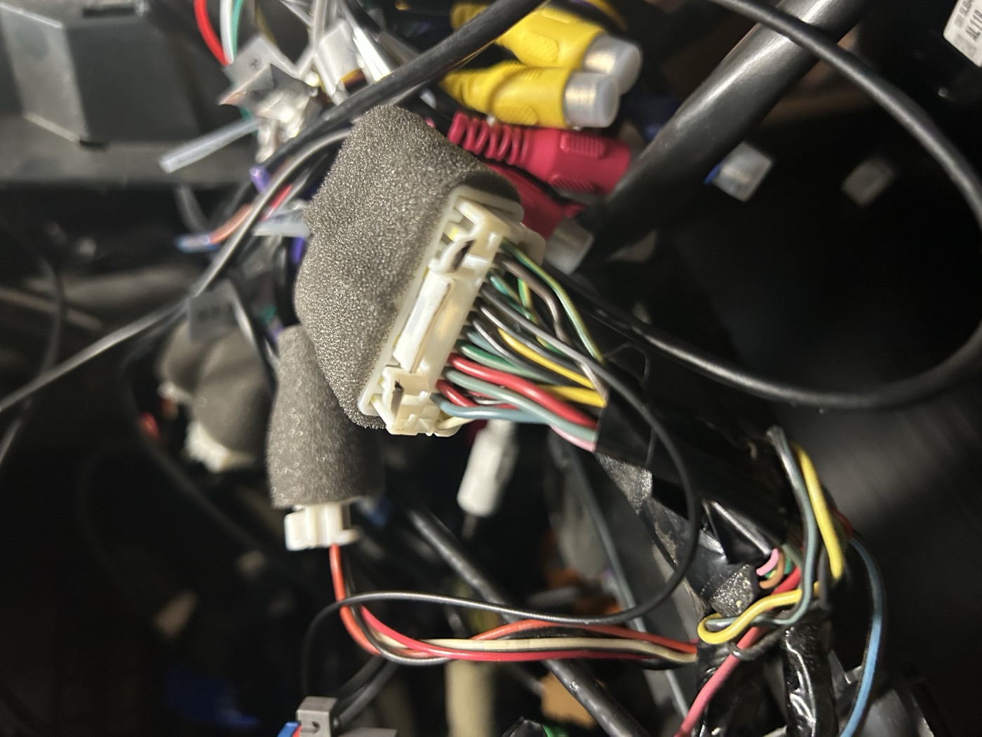
A white multi-way connector on the radio harness with a red wire running into a small separate white housing below it — the added 5V feed for the microphone.
The microphone's 5 V feedPin 4 of the radio harness is an empty cavity from the factory, and this is the wire that fills it. The connector all of this hangs off is the one at the top of the page.

Six solder joints, and one wire that was never there

Bridging connector B turns a dead module into a passive loop-back and the audio path closes again. Every pair below is one signal that entered the module on one pin and left it on the other.

JumperRestores
B1 – B2Front speaker LH -
B3 – B4Front speaker RH -
B5 – B6Microphone signal
B9 – B10Front speaker LH +
B11 – B12Front speaker RH +
B13 – B14Microphone ground
B8Microphone 5 V — not a jumper. A wire from pin 4 of the radio harness.

This is a record of what worked on one car, not a service procedure. Pin numbering varies by trim and by model year, and the figures here are transcribed from one factory service manual page for one car. Verify against your own harness before cutting anything, and disconnect the battery first.

What the A side exposes is the other half of the story, and the reason there is a project at all:

Two CAN buses, not one

MAIN CAN on A17 and A7, BODY CAN on A6 and A16. They are separate networks rather than a second tap on the same wires, and OBD-II lives on the powertrain side — so MAIN is the pair to try first, and the bit rate is worth confirming before either is trusted.

Three power rails

Battery on A10, ignition on A8, accessory on A20 — all 9 to 16 V, with chassis ground on A14. Permanent power to stay alive, and two switched rails that say what the car is doing without asking it.

Two buttons and two LEDs

The SOS button on A5 and the i-button on A4, each switching to ground rather than presenting a pair, so both want a pull-up. Green on A3 and red on A13, single-ended against that same A14 ground. Console controls with nothing left to call.

And two to be curious about

MUTE on A19 and Collision detection signal on A18. Both are listed in the service manual without further explanation, and both are still on the list of things to put a scope on.

A tester that survives a real bus

An Arduino Nano ESP32 with an MCP2515 on SPI, speaking standard ISO 15765-4 at 500 kbit/s with 11-bit identifiers — so nothing changes between the bench and the driveway. A functional request on 0x7DF reaches every ECU; 0x7E0+n addresses one; 0x7E8+n is how it answers.

Every command is a transaction with a reply and a deadline, not a frame fired into the dark. An unplugged node reads as "no response" rather than looking identical to success — which is the difference between a tool you can believe and a tool that agrees with you.

ISO-TP, properly

Segmented transfers with flow control, block size and STmin pacing, and the timeout paths that matter when a node stops answering half-way through a reply.

Eight reassembly channels

One per possible ECU. A broadcast can put two segmented replies on the wire at the same time, and a single shared buffer would splice them into nonsense.

Hardware acceptance filters

Three separate traps in the MCP2515 driver make filters fail silently — including one where asking for a mask of 0x7FF writes a mask of zero and accepts every frame on the bus. All three are handled, and written down.

114 checks, no hardware

Frame bytes, flow control, pacing, timeouts, DTC and PID codecs and the filter register encoding — plus an integration suite that compiles the three real sketches unmodified and runs them against each other on a simulated bus.

A seam where the app goes

Everything the tester prints goes through a single Print *. Swapping the serial console for a Bluetooth LE characteristic is a one-line change, because nothing below that line knows which one it is talking to.

Two mock ECUs on the bench

Segmented responses, several ECUs answering one broadcast, and an ECU that stays silent — all exercised on a desk instead of on a driveway. Scaffolding, not product.

Read the sketches

The tester is one sketch. Everything else in the tree exists to give it something to talk to, or to prove it works without a car attached.

The two followers below are bench scaffolding. They pretend to be an engine ECU and a transmission ECU so that the hard paths can be exercised on a desk — they are reference material, and no part of what goes in the car.

A phone app, eventually

The plan is one app on both phones, talking to the tester over Bluetooth LE — the tester's console output already runs through a single seam built for exactly that swap. Neither app exists yet, and neither is going to a store when it does.

Placeholder — iOS Not published Placeholder — Android Not published

These two slots are here so the page has somewhere to put them if that ever changes.

This site is information, not a shop

There is nothing to download here, and that is deliberate rather than unfinished. Scan Hippo plugs into a connector that only exists in one generation of one model, behind a dash, on a car whose telematics module has already been removed. Shipping it would mean shipping a wiring harness, a board and a fair amount of liability into somebody else's 12 V electrical system — which is not something a hobby project gets to do casually, and not something this one is set up for.

So the code is public to read, the wiring is written down, and the pinout is in the repository for the next person who finds a dead StarLink module and wonders what the other half of the connector does. Maybe one day it gets productised. Today it is a story with a soldering iron in it.